Towards Spontaneous Interaction with the
Perceptive Workbench, a
Semi-Immersive Virtual Environment
Bastian Leibe, Thad Starner, William Ribarsky, Zachary Wartell, David
Krum, Justin Weeks, Brad Singletary, and Larry Hodges
GVU Center, Georgia Institute of Technology
Abstract
The Perceptive Workbench enables a spontaneous and unimpeded
interface between the physical and virtual worlds. It uses vision-based
methods for interaction that eliminate the need for wired input devices and
wired tracking. Objects are recognized and tracked when placed on the
display surface. Through the use of multiple infrared light sources, the
object's 3D shape can be captured and inserted into the virtual interface.
This ability permits spontaneity since either preloaded objects or those objects
selected on the spot by the user can become physical icons. Integrated
into the same vision-based interface is the ability to identify 3D hand
position, pointing direction, and sweeping arm gestures. Such gestures can
enhance selection, manipulation, and navigation tasks. In this paper, the
Perceptive Workbench is used for augmented reality gaming and terrain navigation
applications, which demonstrate the utility and flexibility of the
interface.
1. Introduction
Until now, we have interacted with computers mostly by
using devices that are constrained by wires. Typically, the wires limit the
distance of movement and inhibit freedom of orientation. In addition, most
interactions are indirect. The user moves a device as an analogue for the
action to be created in the display space. We envision an interface
without these restrictions. It is untethered; accepts direct, natural
gestures; and is capable of spontaneously accepting as interactors any objects
we choose.
In conventional 3D interaction, the devices that track position
and orientation are still usually tethered to the machine by wires.
Devices, such as pinch gloves, that permit the user to experience a more
natural-seeming interface often do not perform as well and are less preferred
with users, than simple handheld devices with buttons [Kessler95,
Seay99].
Pinch gloves carry assumptions about the position of the user's hand and
fingers with respect to the tracker. Of course, users' hands differ
in size and shape, so the assumed tracker position must be recalibrated for each
user. This is hardly ever done. Also, the glove interface causes
subtle changes to recognized hand gestures. The result is that fine
manipulations can be imprecise, and the user comes away with the feeling that
the interaction is slightly off in an indeterminate way. If we can
recognize gestures directly, we take into account the difference in hand sizes
and shapes.
An additional problem is that any device held in the hand can become awkward
while gesturing. We have found this even with a simple pointing device,
such as a stick with a few buttons [Seay99].
Also a user, unless fairly skilled, often has to pause to identify and select
buttons on the stick. With accurately tracked hands most of this
awkwardness disappears. We are adept at pointing in almost any direction
and can quickly pinch fingers, for example, without looking at them.
Finally, physical objects are often natural interactors (such as phicons [Ullmer97]).
However, with current systems these objects must be inserted in advance or
specially prepared. One would like the system to accept objects that one
chooses spontaneously for interaction.
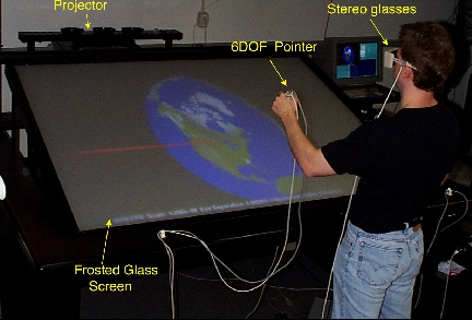 |
Figure 1: A user interacting
with Georgia Tech's Virtual Workbench using a 6DoF
pointer.
In this paper we discuss
methods for producing more seamless interaction between the physical and virtual
environments through the creation of the Perceptive Workbench. The system
is then applied to an augmented reality game and a terrain navigating
system. The Perceptive Workbench can reconstruct 3D virtual
representations of previously unseen real-world objects placed on its
surface. In addition, the Perceptive Workbench identifies and tracks such
objects as they are manipulated on the desk's surface and allows the user to
interact with the augmented environment through 2D and 3D gestures. These
gestures can be made on the plane of the desk's surface or in the 3D space above
the desk. Taking its cue from the user's actions, the Perceptive Workbench
switches between these modes automatically, and all interaction is controlled
through computer vision, freeing the user from the wires of traditional sensing
techniques.
2. Related Work
While the Perceptive Workbench [Leibe00]
is unique in its extensive ability to interact with the physical world,
it has a rich heritage of related work [Arai95,
Bimber99,
Coquillart99,
Kobayashi98,
Krueger91,
Krueger95,
May99,
Rekimoto97,
Schmalstieg99,
Seay99,
Ullmer97,
Underkoffler98,
vdPol99,
Wellner93].
Many augmented desk and virtual reality designs use tethered props, tracked by
electromechanical or ultrasonic means, to encourage interaction through
manipulation and gesture [Bolt92,
Bimber99,
Coquillart99,
Schmalstieg99,
Seay99,
Sturman92,
vdPol99].
Such designs tether the user to the desk and require the time-consuming ritual
of donning and doffing the appropriate equipment.
Fortunately, the computer vision community has taken up
the task of tracking the user's hands and identifying gestures. While
generalized vision systems track the body in room and desk-based scenarios for
games, interactive art, and augmented environments [Bobick96,
Wren95,
Wren97],
reconstruction of fine hand detail involves carefully calibrated systems and is
computationally intensive [Rehg93].
Even so, complicated gestures such as those used in sign language [Starner98,
Vogler98]
or the manipulation of physical objects [Sharma97]
can be recognized. The Perceptive Workbench uses computer vision techniques to
maintain a wireless interface.
Most directly related to the Perceptive Workbench, the "Metadesk" [Ullmer97]
identifies and tracks objects placed on the desk's display surface using a
near-infrared computer vision recognizer, originally designed by Starner.
Unfortunately, since not all objects reflect infrared light and infrared shadows
are not used, objects often need infrared reflective "hot mirrors" placed in
patterns on their bottom surfaces to aid tracking and identification. Similarly,
Rekimoto and Matsushita's "Perceptual Surfaces" [Rekimoto97]
employ 2D barcodes to identify objects held against the "HoloWall" and
"HoloTable." In addition, the HoloWall can track the user's hands (or other body
parts) near or pressed against its surface, but its potential recovery of the
user's distance from the surface is relatively coarse compared to the 3D
pointing gestures of the Perceptive Workbench. Davis and Bobick's SIDEshow [Davis98]
is similar to the Holowall except that it uses cast shadows in infrared for
full-body 2D gesture recovery. Some augmented desks have cameras and projectors
above the surface of the desk and are designed to augment the process of
handling paper or interacting with models and widgets through the use of
fiducials or barcodes [Arai95,
Kobayashi98,
Underkoffler98,
Wellner93].
Krueger's VIDEODESK [Krueger91],
an early desk-based system, used an overhead camera and a horizontal visible
light table (for high contrast) to provide hand gesture input for interactions
displayed on a monitor on the far side of the desk. In contrast with the
Perceptive Workbench, none of these systems address the issues of introducing
spontaneous 3D physical objects into the virtual environment in real-time and
combining 3D deictic (pointing) gestures with object tracking and
identification.
3. Apparatus
The display environment for the Perceptive Workbench is
based on Fakespace's immersive workbench, consisting of a wooden desk
with a horizontal frosted glass surface on which a stereoscopic image can be
projected from behind the Workbench.
 |
 |
Figure 2: Light and camera positions for the
Perceptive Workbench.
The top view shows how shadows are cast and
the 3D arm position is tracked.
We placed a
standard monochrome surveillance camera under the projector that watches the
desk surface from underneath (see Figure
2). A filter placed in front of the camera lens makes it insensitive to
visible light and to images projected on the desk's surface. Two infrared
illuminators placed next to the camera flood the surface of the desk with
infrared light that is reflected toward the camera by objects placed on the
desk's surface (Figure
4).
A ring of seven similar light-sources is mounted on the ceiling surrounding
the desk (Figure
2). Each computer-controlled light casts distinct shadows on the
desk's surface based on the objects on the table (Figure
3a). A second camera, this one in color, is placed next to the desk to
provide a side view of the user's arms (Figure
3b). This side camera is used solely for recovering 3D pointing gestures.
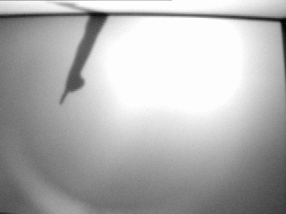 |
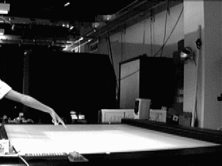 |
Figure 3: Images seen by the infrared and color
cameras: (a) arm shadow from ceiling IR lights;
(b) image from side
camera
We decided to use near-infrared light since it is invisible to the
human eye. Thus, illuminating the scene with it does not interfere with
the user's interaction. Neither the illumination from the IR light
sources underneath the table, nor the shadows cast from the overhead lights can
be observed by the user. On the other hand, IR light can still be seen by
most standard CCD cameras. This makes it a very inexpensive method for
observing the interaction. In addition, by equipping the camera with an infrared
filter, the camera image can be analyzed regardless of changes in (visible)
scene lighting.
All vision processing is done on two SGI R10000 O2s (one for each camera),
which communicate with a display client on an SGI Onyx via sockets.
However, the vision algorithms could also be run on one SGI with two digitizer
boards or be implemented using inexpensive, semi-custom signal-processing
hardware.
We use this setup for three different kinds of interaction which
will be explained in more detail in the following sections: recognition and
tracking of objects placed on the desk surface based on their contour, full 3D
reconstruction of object shapes on the desk surface from shadows cast by the
ceiling light-sources, and recognition and quantification of hand and arm
gestures.
For display on the Perceptive Workbench, we use the Simple Virtual
Environment Toolkit (SVE), a graphics and sound library developed by the Georgia
Tech Virtual Environments Group [Kessler97].
SVE permits us to rapidly prototype applications used in this work. In
addition we use the workbench version of VGIS, a global terrain visualization
and navigation system [Lindstrom96,
Lindstrom97]
as an application for interaction using hand and arm gestures. The workbench
version of VGIS has stereoscopic rendering and an intuitive interface for
navigation [Wartell99a,
Wartell99b].
Both systems are built on OpenGL and have both SGI and PC implementations.
4. Object Tracking & Recognition
As a basic building block for our
interaction framework, we want to enable the user to manipulate the virtual
environment by placing objects on the desk surface. The system should
recognize these objects and track their positions and orientations while they
are being moved over the table. The user should be free to pick any set of
physical objects he wants to use.
The
motivation behind this is to use physical objects in a graspable user interface
[Fitzmaurice95].
Physical objects are often natural interactors (such as "phicons" [Ullmer97]).
They can provide physical handles to control the virtual application in a way
that is very intuitive for the user [Ishii97].
In addition, the use of objects encourages two-handed direct manipulation and
allow parallel input specification, thereby improving the communication
bandwidth with the computer. [Fitzmaurice95,
Ishii97].
To achieve this goal, we use an improved version of the technique described
in Starner et al. [Starner00].
The underside of the desk is illuminated by two near-infrared light-sources (Figure
2). Every object close to the desk surface (including the user's
hands) reflects this light and can be seen by the camera under the display
surface (Figure
4). Using a combination of intensity thresholding and background
subtraction, we extract interesting regions of the camera image and analyze
them. The resulting blobs are classified as different object types based on a
set of features, including area, eccentricity, perimeter, moments, and the
contour shape.
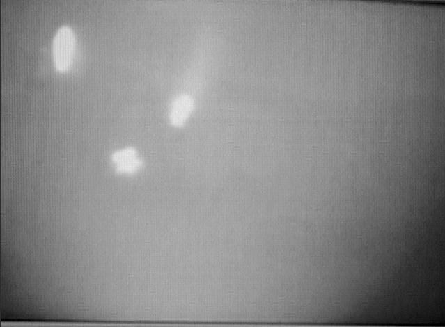 |
Figure 4: Image of reflection from the IR lights
underneath the desk, as seen from the infrared
camera.
There are several complications due
to the hardware arrangement. The foremost problem is that our two light sources
under the table can only provide a very uneven lighting over the whole desk
surface, bright in the middle, and getting weaker toward the borders. In
addition, the light rays are not parallel, and the reflection on the mirror
surface further exacerbates this effect. As a result, the perceived sizes and
shapes of objects on the desk surface can vary depending on position and
orientation. Finally, when the user moves an object, the reflection from his
hand can also add to the perceived shape. This makes it necessary to use an
additional stage in the recognition process that matches recognized objects to
objects known to be on the table and that can filter out wrong classification or
even handle complete loss of information about an object for several frames.
In this work, we are using the object recognition and tracking capability
mainly for "cursor objects". Our focus is on fast and accurate position
tracking, but the system may be trained on a different set of objects to be used
as navigational tools or physical icons [Ullmer97].
A future project will explore different modes of interaction based on this
technology.
5. Deictic Gesture Tracking
Hand gestures can be roughly classified into
symbolic (iconic, metaphoric, and beat) and deictic (pointing) gestures. Symbolic gestures carry an abstract meaning that may still be
recognizable in iconic form in the associated hand movement. Without the
necessary cultural context, however, the meaning may be arbitrary. Examples for
symbolic gestures include most conversational gestures in everyday use, and
whole gesture languages, for example, American Sign Language. Previous work by
Starner [Starner98]
has shown that a large set of symbolic gestures can be distinguished and
recognized from live video images using hidden Markov models
(HMMs).
Deictic gestures, on the other hand, are characterized by a
strong dependency on location and orientation of the performing hand. Their
meaning is determined by the location at which a finger is pointing, or by the
angle of rotation of some part of the hand. This information acts not only as a
symbol for the gesture's interpretation, but also as a measure of by how
much the corresponding action should be executed or to which object it should be
applied.
For navigation and object manipulation in a virtual environment, many
gestures are likely to have a deictic component. It is usually not enough to
recognize that an object should be rotated, but we will also need to know the
desired amount of rotation. For object selection or translation, we want to
specify the object or location of our choice just by pointing at it. For these
cases, gesture recognition methods that only take the hand shape and trajectory
into account will not be sufficient. We need to recover 3D information about the
user's hand and arm in relation to his body.
In the past, this information has largely been obtained by using
wired gloves or suits, or magnetic trackers [Bolt92,
Bimber99].
Such methods provide sufficiently accurate results but rely on wires and have to
be tethered to the user's body, or to specific interaction devices, with
all the aforementioned problems. Our goal is to develop a purely vision-based
architecture that facilitates unencumbered 3D interaction.
With vision-based 3D tracking techniques, the first issue is to determine
which information in the camera image is relevant, i.e. which regions represent
the user's hand or arm. This task is made even more difficult by
variation in user clothing or skin color and by background activity. Although typically only one user interacts with the environment at
a given time using traditional methods of interaction, the physical dimensions
of large semi-immersive environments such as the workbench invite people to
watch and participate.
In a virtual workbench environment, there are few places
where a camera can be placed to provide reliable hand position
information. One camera can be set up next to the table without overly
restricting the available space for users, but if a similar second camera were
to be used at this location, either multi-user experience or accuracy would be
compromised. We have addressed this problem by employing our shadow-based
architecture (as described in the hardware
section). The user stands in front of the workbench and extends an arm over
the surface. One of the IR light-sources mounted on the ceiling to the left of,
and slightly behind the user, shines its light on the desk surface, from where
it can be seen by the IR camera under the projector (see Figure
5). When the user moves his arm over the desk, it casts a shadow on the desk
surface (see Figure
6a). From this shadow, and from the known light-source position, we can
calculate a plane in which the user's arm must lie.
 |
Figure 5: Principle of
pointing direction recovery.
Simultaneously, the second camera to the right of the table (Figure
5 and Figure
7a) records a side view of the desk surface and the user's arm. It
detects where the arm enters the image and the position of the fingertip. From
this information, it extrapolates two lines in 3D space, on which the observed
real-world points must lie. By intersecting these lines with the shadow plane,
we get the coordinates of two 3D points, one on the upper arm, and one on the
fingertip. This gives us the user's hand position, and the direction in
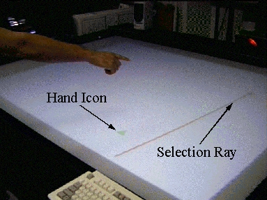
which the user is pointing. As shown in Figure
13a, this information can be used to project a icon for the hand position
and a selection ray in the workbench display.
Obviously, the success of the gesture tracking capability
relies very strongly on how fast the image processing can be done. It is
therefore necessary to use simple algorithms. Fortunately, we can make some
simplifying assumptions about the image content.
We must first
recover arm direction and fingertip position from both the camera and the shadow
image. Since the user is standing in front of the desk and the user's arm
is connected to the user's body, the arm's shadow should always
touch the image border. Thus our algorithm exploits intensity thresholding and
background subtraction to discover regions of change in the image and searches
for areas in which these touch the front border of the desk surface (which
corresponds to the top border of the shadow image or the left border of the
camera image). It then takes the middle of the touching area as an approximation
for the origin of the arm (Figure
6b and Figure
7b). For simplicity we will call this point the "shoulder", although in most
cases it is not. Tracing the contour of the shadow, the algorithm searches for
the point that is farthest away from the shoulder and takes it as the fingertip.
The line from the shoulder to the fingertip reveals the 2D direction of the arm.
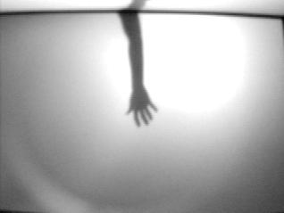 |
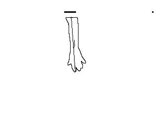 |
Figure 6: (a) Arm shadow from
overhead IR lights; (b) resulting contour with recovered arm
direction.
In our experiments, the
point thus obtained was coincident with the pointing fingertip in all but a few
extreme cases (such as the fingertip pointing straight down at a right angle to
the arm). The method does not depend on a pointing gesture, but also works
for most other hand shapes, including but not restricted to, a hand held
horizontally, vertically or in a fist. These shapes may be distinguished by
analyzing a small section of the side camera image and may be used to trigger
specific gesture modes in the future.
|
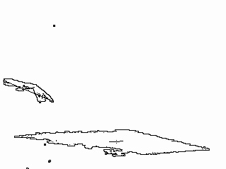 |
Figure 7: (a) image from side camera; (b) arm contour (from similar image) with recovered arm
direction.
The computed arm
direction is correct as long as the user's arm is not overly bent (see Figure
7). In such cases, the algorithm still connected shoulder and fingertip,
resulting in a direction somewhere between the direction of the arm and the one
given by the hand. Although the absolute resulting pointing position did not
match the position towards which the finger was pointing, it still managed to
capture the trend of movement very well. Surprisingly, the technique is
sensitive enough such that the user can stand at the desk with his arm extended
over the surface and direct the pointer simply by moving his index finger,
without arm movement.
Limitations
The architecture used poses several limitations. The primary
problem with the shadow approach is finding a position for the light source that
can give a good shadow of the user's arm for a large set of possible
positions, while avoiding capture of the shadow from the user's body.
Since the area visible to the IR camera is coincident with the desk surface,
there are necessarily regions where the shadow is not visible in, touches, or
falls outside of the borders. Our solution to this problem is to switch
automatically to a different light source whenever such a situation is detected,
the choice of the new light source depending on where the shadows touched the
border. By choosing overlapping regions for all light sources, we can keep the
number of light source switches to a necessary minimum. In practice, four light
sources in the original set of seven were enough to cover the relevant area of
the desk surface. However, an additional spotlight, mounted directly overhead of
the desktop, has been added to provide more direct coverage of the desktop
surface.
Another problem can be seen in Figure
7b, where segmentation based on color background subtraction detects both
the hand and the change in the display on the workbench. A more recent
implementation replaces the side color camera with an infrared spotlight and a
monochrome camera equipped with an infrared-pass filter. By adjusting the angle
of the light to avoid the surface of the desk or any other close objects, the
user's arm is illuminated and made distinct from the background and changes in
the workbench's display does not affect the tracking.
A bigger problem is caused by the actual location of the side camera. If the
user extends both of his arms over the desk surface, or if more than one user
tries to interact with the environment at the same time, the images of these
multiple limbs can overlap and be merged to a single blob. As a consequence, our
approach will fail to detect the hand positions and orientations in these cases.
A more sophisticated approach using previous position and movement information
could yield more reliable results, but we chose, at this first stage, to accept
this restriction and concentrate on high frame rate support for one-handed
interaction. This may not be a serious limitation for a single user for certain
tasks; a recent study shows that for a task normally requiring
two hands in
a real environment, users have no preference for one versus two hands in a
virtual environment that does not
model effects such as gravity and inertia
[Seay99].
6. 3D Reconstruction
To complement the capabilities
of the Perceptive Workbench, we want to be able to insert real objects into the
virtual world and to share them with other users at different locations. An
example application for this could be a telepresence or computer-supported
collaborative work (CSCW) system. Instead of verbally describing an object, the
user would be able to quickly create a 3D reconstruction and send it to his
co-workers (see Figure
8). For this, it is necessary to design a reconstruction mechanism that does
not interrupt the interaction. Our focus is providing an almost instantaneous
visual cue for the object as part of the interaction, not necessarily on
creating a highly accurate model.
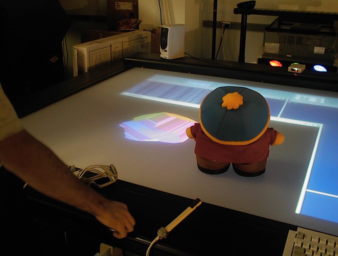 |
Figure 8: Real object
inserted into the virtual world.
Several methods have been designed to reconstruct objects from silhouettes
[Srivastava90,
Sullivan98]
or dynamic shadows [Daum98]
using either a moving camera or light-source on a known trajectory or a
turntable for the object [Sullivan98].
Several systems have been developed for the reconstruction of relatively simple
objects, including the commercial system Sphinx3D.
However, the necessity to move either the camera or the object imposes severe
constraints on the working environment. To reconstruct an object with these
methods, it is usually necessary to interrupt the user's interaction with
it, take the object out of the user's environment, and place it into a
specialized setting (sometimes in a different room). Other approaches make use
of multiple cameras from different view points to avoid this problem at the
expense of more computational power to process and communicate the results.
In this project, using only one camera and the infrared light sources, we
analyze the shadows cast on the object from multiple directions (see Figure
9). As the process is based on infrared light, it can be applied
independently of the lighting conditions and without interfering with the user's
natural interaction with the desk.
The existing approaches to reconstruct shape from shadows
or silhouettes can be divided into two camps. The volume approach, pioneered by
Baumgart [Baumgart74]
intersects view volumes to create a representation for the object. Common
representations for the resulting model are polyhedra [Baumgart74,
Conolly89],
or octrees [Srivastava90,
Chien86].
The surface approach reconstructs the surface as the envelope of its tangent
planes. It has been realized in several systems [Boyer96,
Seales95].
Both approaches can be combined, as in Sullivan's work [Sullivan98],
which uses volume intersection to create an object and then smooths the surfaces
with splines.
We have chosen to use a volume approach to create
polyhedral reconstructions for several reasons. We want to create models that
can be used instantaneously in a virtual environment. Our focus is not on
getting a photorealistic reconstruction, but on creating a quick low
polygon-count model for an arbitrary real-world object in real-time, without
interrupting the ongoing interaction. Polyhedral models offer significant
advantages over other representations, such as generalized cylinders,
superquadrics, or polynomial splines. They are simple and computationally
inexpensive, Boolean set operations can be performed on them with reasonable
effort, and most current VR engines are optimized for fast rendering of
polygonal scenes. In addition, polyhedral models are the basis for many later
processing steps. If desired, they can still be refined with splines using a
surface approach.
 |
Figure 9: Principle of the 3D
reconstruction.
To obtain the different
views, we mounted a ring of seven infrared light sources in the ceiling, each
one of which is switched independently by computer control. The system detects
when a new object is placed on the desk surface, and the user can initiate the
reconstruction by touching a virtual button rendered on the screen (Figure
13). This action is detected by the camera, and, after only one second, all
shadow images are taken. In another second, the reconstruction is complete (Figure
12), and the newly reconstructed object is part of the virtual world.
Our approach is fully automated and does not require any special hardware
(e.g. stereo cameras, laser range finders, structured lighting,
etc.). The method is extremely inexpensive, both in hardware and in
computational cost. In addition, there is no need for extensive calibration,
which is usually necessary in other approaches to recover the exact position or
orientation of the object in relation to the camera. We only need to know
the approximate position of the light-sources (+/- 2 cm), and we need to adjust
the camera to reflect the size of the display surface, which must be done only
once. Neither the camera, light-sources, nor the object are moved during
the reconstruction process. Thus recalibration is unnecessary. We
have substituted for all mechanical moving parts, which are often prone to wear
and imprecision, by a series of light beams from known locations.
An obvious limitation for this approach is that we are confined to a fixed
number of different views from which to reconstruct the object. The turntable
approach, on the other hand, allows the system to take an arbitrary number of
images from different view points. However, Sullivan's work [Sullivan98]
and our experience with our system have shown that even for quite complex
objects, usually seven to nine different views are enough to get a reasonable 3D
model of the object. Note that the reconstruction uses
the same hardware as the deictic gesture tracking capability discussed in the
previous section. Thus, it comes at no additional cost.
The speed of the reconstruction process is mainly limited by the switching
time of the light sources. Whenever a new light-source is activated, the image
processing system has to wait for several frames to receive a valid image. The
camera under the desk records the sequence of shadows cast by an object on the
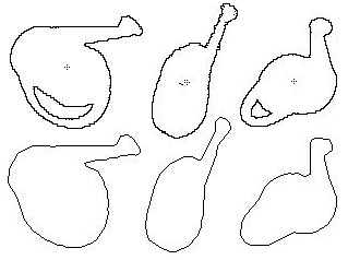
table when illuminated by the different lights. Figure
10 shows two series of contour shadows extracted from two sample objects by
using different IR sources. By approximating each shadow as a polygon (not
necessarily convex) [Rosin95],
we create a set of polyhedral "view cones", extending from the light source to
the polygons. The intersection of these cones creates a polyhedron that roughly
contains the object. Figure
11 shows some more shadows with the resulting
polygons and a visualization of the intersection of polyhedral cones.
 |
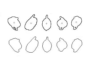 |
Figure 10: Shadow contours
and interpolated polygons from a watering can (left) and a teapot
(right).
Intersecting non-convex polyhedral objects is a very
complex problem, further complicated by numerous special cases that have to be
taken care of. Fortunately, this problem has already been exhaustively
researched, and solutions are available [Mantyla88].
For the intersection calculations in our application, we used Purdue
University's TWIN Solid Modeling Library [TWIN95].
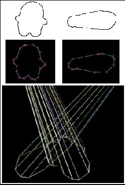 |
Figure 11: Steps of 3D object reconstruction
including extraction of contour shapes from shadows
and intersection
of multiple view cones (bottom).
Figure
13b shows a freshly reconstructed model of a watering can placed on the desk
surface. The same model can be seen in more detail in Figure
12, along with the reconstruction of a teapot. The colors were chosen to
highlight the different model faces by interpreting the face normal as a vector
in RGB color space.
 |
 |
 |
 |
 |
 |
Figure 12: 3D reconstruction
of the watering can seen in Figure 5-5 (top) and a teapot
(bottom).
The colors are chosen to
highlight the model faces.
Limitations
An obvious
limitation to our approach is that not every non-convex object can be exactly
reconstructed from its silhouettes or shadows. The closest approximation
that can be obtained with volume intersection is its visual hull. But even
for objects with a polyhedral visual hull an unbounded number of silhouettes may
be necessary for an exact reconstruction [Laurentini97].
In practice, we can get sufficiently accurate models for a large variety of
real-world objects, even from a relatively small number of different
views.
Exceptions are spherical or cylindrical objects.
The quality of reconstruction for these objects depends largely on the number of
available views. With only seven light-sources, the resulting model will appear
faceted. This problem can be solved by either adding more light-sources,
or by improving the model with the help of splines.
Apart from this, the accuracy by which objects can be
reconstructed is bounded by another limitation of our architecture. All
our light-sources are mounted to the ceiling. From this point of view they
cannot provide full information about the object's shape. There is
a pyramidal "blind spot" above all horizontal flat surfaces that the
reconstruction cannot eliminate. The slope of these pyramids depends on
the angle between the desk surface and the rays from the light-sources.
For our current hardware setting, this angle ranges between 37° and 55°,
depending on the light-source. Only structures with a greater slope will
be reconstructed entirely without error. This problem is intrinsic to the
method and does also occur with the turntable approach, but on a much smaller
scale.
We
expect that we can greatly reduce the effects of this error by using the image
from the side camera and extracting an additional silhouette of the object from
this point of view. This will help to keep the error angle well below
10°. Calculations based on the current position of the side camera
(optimized for the gesture recognition) promise an error angle of only
7°.
In the current version of our software, an additional
error is introduced through the fact that we are not yet handling holes in the
shadows. But this is merely an implementation issue, which will be
resolved in a future extension to our project.
7. Performance Analysis
Object and Gesture Tracking
Both object and
gesture tracking perform at a stable 12-18 frames per second. Frame rate
depends on the number of objects on the table and the size of the shadows,
respectively. Both techniques are able to follow fast motions and
complicated trajectories. Latency is currently 0.25-0.33 seconds but has
improved since last testing (an acceptable threshold is typically around 0.1
second). Surprisingly, this level of latency seems adequate for most
pointing gestures in our current applications. Since the user is provided
with continuous feedback about his hand and pointing position, and most
navigation controls are relative rather than absolute, the user adapts his
behavior readily to the system. With object tracking, the physical object
itself can provide the user with adequate tactile feedback as the system catches
up with the user's manipulations. In general, since the user is moving
objects across a very large desk surface, the lag is noticeable but rarely
troublesome in the current applications.
Even so, we expect that simple improvements in the socket communication
between the vision and rendering code and in the vision code itself will improve
latency significantly. For the terrain navigation task below, rendering
speed provides a limiting factor. However, Kalman filters may compensate
for render lag and will also add to the stability of the tracking system.
3D Reconstruction
Calculating the error from
the 3D reconstruction process requires choosing known 3D models, performing the
reconstruction process, aligning the reconstructed model and the ideal model,
and calculating an error measure. For simplicity, a cone and pyramid were
chosen. The centers of mass of the ideal and reconstructed models were set
to the same point in space, and their principal axes were aligned.
To measure error, we used the Metro tool [Cignoni98].
It approximates the real distance between the two surfaces by choosing a set of
(100,000-200,000) points on the reconstructed surface, and then calculating the
two-sided distance (Hausdorff distance) between each of these points and the
ideal surface. This distance is defined as

with E(S1,S2) denoting the one-sided distance between the surfaces S1 and S2:

The Hausdorff distance directly corresponds to the reconstruction
error. In addition to the maximum distance, we also calculated the mean
and mean square distances. Table
1 shows the results. In these examples, the relatively large maximal
error was caused by the difficulty in accurately reconstructing the tip of the
cone and the pyramid.
| |
Cone |
Pyramid |
|
Maximal Error |
0.0215 (7.26 %) |
0.0228 (6.90 %) |
|
Mean Error |
0.0056 (1.87 %) |
0.0043 (1.30 %) |
|
Mean Square Error |
0.0084 (2.61 %) |
0.0065 (1.95 %) |
Table 1: Reconstruction errors averaged over three
runs
(in meters and percentage of object
diameter).
While improvements may be made
by precisely calibrating the camera and lighting system, by adding more light
sources, and by obtaining a silhouette from the side camera (to eliminate
ambiguity about the top of the surface), the system meets its goal of providing
virtual presences for physical objects in a quick and timely manner that
encourages spontaneous interactions.
8. Putting It to Use: Spontaneous Gesture Interfaces
All the components of the Perceptive Workbench, deictic gesture
tracking, object recognition, tracking, and reconstruction, can be combined into
a single, consistent framework. The Perceptive Workbench interface detects how
the user wants to interact with it and automatically switches to the desired
mode.
When the user moves his hand above the display surface, the hand and arm are
tracked as described in Section
4. A cursor appears at the projected hand position on the display surface,
and a ray emanates along the projected arm axis. These can be used in selection
or manipulation, as in Figure
13a. When the user places an object on the surface, the cameras recognize
this and identify and track the object. A virtual button also appears on the
display (indicated by the arrow in Figure
13b). Through shadow tracking, the system determines when the hand overlaps
the button, selecting it. This action causes the system to capture the 3D object
shape, as described in Section
5.
 |
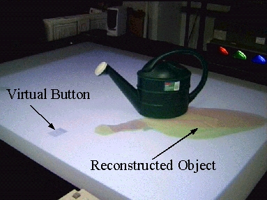 |
Figure 13: (a) Pointing gesture with hand icon
and selection ray; (b) Virtual button
rendered on the screen when
object is detected on the surface.
The decision whether or not
there is an object on the desk surface is made easy by the fact that shadows
from the user's arms always touch the image border. Thus, if a shadow is
detected that does not touch any border, the system can be sure that it is
caused by an object on the desk surface. As a result, it will switch to object
recognition and tracking mode. Similarly, the absence of such shadows, for a
certain period, indicates that the object has been taken away, and the system
can safely switch back to gesture tracking mode. Note that once the system is in
object recognition mode, the ceiling lights are switched off, and the light
sources underneath the table are activated instead. It is therefore safe for the
user to grab and move objects on the desk surface, since his arms will not cast
any shadows that could disturb the perceived object contours.
This set provides the elements of a perceptual interface, operating without
wires and without restrictions as to objects employed. For example, we have
constructed a simple application where objects placed on the desk are selected,
reconstructed, and then placed in a "template" set, displayed as slowly rotating
objects on the left border of the workbench display. These objects can then be
grabbed by the user and could act as new physical icons that are attached by the
user to selection or manipulation modes. Or the shapes themselves could be used
in model-building or other applications.
An Augmented Reality Game
We have created a more elaborate collaborative
interface using the Perceptive Workbench. This involves the workbench
communicating with a person in a separate space wearing an augmented reality
headset. All interaction is via image-based gesture tracking without attached
sensors. The game is patterned after a martial arts fighting game. The user in
the augmented reality headset is the player, and one or more people interacting
with the workbench are the game masters. The workbench display surface acts as a
top-down view of the player's space. The game masters place different
objects on the surface, which appear to the player as distinct monsters at
different vertical levels in his space. The game masters move the objects around
the display surface, toward and away from the player; this motion is replicated
in the player's view by the monsters which move in their individual planes. Figure
14a shows the game masters moving objects, and Figure
15b displays the moving monsters in the virtual space.
 |
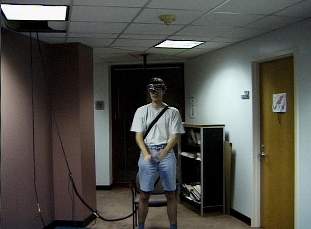
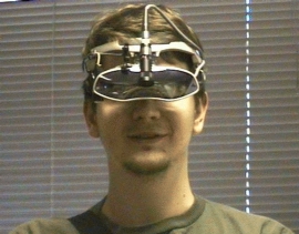 |
Figure 14: (a) Two game
masters controlling virtual monsters; (b) hardware outfit worn by mobile
player.
The mobile player wears a
"see-through" Sony Glasstron (Figure
14b) equipped with two cameras. Fiducials or natural features in the
player's space are tracked by the forward facing camera to recover head
orientation. This allows graphics (such as monsters) to be rendered roughly
registered with the physical world. The second camera looks down at the
player's hands to recognize "martial arts" gestures [Starner98].
 |
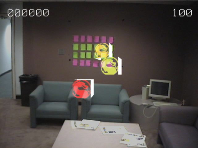 |
Figure 15: (a) Mobile player
performing Kung-Fu gestures to ward off monsters;
(b) Virtual monsters overlayed on the real background as seen by
the mobile player.
While a more
sophisticated hidden Markov model system is under development, a simple template
matching method is sufficient for recognizing a small set of martial arts
gestures. To effect attacks on the monsters, the user accompanies the
appropriate attack gesture (Figure
15a) with a Kung Fu yell ("heee-YAH"). Each foe requires a different
gesture. Foes that are not destroyed enter the player's personal space
and injure him. Enough injuries will cause the player's defeat.
The system has been used by faculty and graduate students in the
GVU lab. They have found the experience compelling and balanced. Since it is
difficult for the game master to keep pace with the player, two or more game
masters may participate (Figure
14a). The Perceptive Workbench's object tracker scales naturally to
handle multiple, simultaneous users. For a more detailed description of this
application, see Starner et al. [Starner00].
3D Terrain Navigation
We have developed a global terrain navigation
system on the virtual workbench which allows one to fly continuously from outer
space to terrain or buildings with features at one foot or better resolution [Wartell99a].
Since features are displayed stereoscopically [Wartell99b],
the navigation is both compelling and detailed. In our third person
navigation interface, the user interacts with the terrain as if it were an
extended relief map laid out below one on a curved surface. Main
interactions include zooming, panning, and rotating. Since the user is
head-tracked he can move his head to look at the 3D objects from different
angles. Previously, interaction has been by using button sticks with six
degrees of freedom electromagnetic trackers attached. We employ the
deictic gestures of the Perceptive Workbench, as described in Section
5, to remove this constraint. Direction of navigation is chosen by
pointing and can be changed continuously (Figure
16c). Moving the hand towards the display increases speed towards the
earth and moving it away increases speed away from the earth. Panning is
accomplished by lateral gestures in the direction to be panned (Figure
16a). Rotation is accomplished by making a rotating gesture with the
arm (Figure
16b). At present these three modes are chosen by keys on a keyboard
attached to the workbench. In the future we expect to use gestures
entirely (e.g., pointing will indicate zooming).
Although there are currently some problems with latency and accuracy (both of
which will be diminished in the future), a user can successfully employ gestures
for navigation. In addition the set of gestures are quite natural to
use. Further, we find that the vision system can distinguish hand
articulation and orientation quite well. Thus we will be able to attach
interactions to hand movements (even without the larger arm movements). At the
time of this writing, an HMM framework has been developed to allow the user to
train his own gestures for recognition. This system, in association with the
terrain navigation database, should allow more sophisticated interactions in the
future.
 |
 |
 |
Figure 16: Terrain navigation using deictic
gestures: (a) panning; (b) rotation (about an axis perpendicular to
and through the end of the rotation lever); (c) zooming
in.
Telepresence, CSCW
As
another application of the Perceptive Workbench, we have built a small
telepresence system. Using the sample interaction framework described at the
beginning of this section, a user can point to any location on the desk,
reconstruct objects, and move them across the desk surface. Every one of his
actions is immediately applied to a virtual reality model of the workbench
mirroring the current state of the real desk. Thus, when performing deictic
gestures, the current hand and pointing position is displayed on the model
workbench by a red selection ray. Similarly, the reconstructed shapes of objects
on the desk surface are displayed at the corresponding positions in the model
(Figure
17). This makes it possible for co-workers at a distant location to follow
the user's actions in real-time, while having complete freedom to choose
a favorable view point.
 |
Figure 17: An example for a
telepresence system: A virtual instantiation of the
workbench
mirroring, in
real-time, the type and position of objects placed on the real
desk.
9. Future Work and Conclusions
Several improvements can be made to the
Perceptive Workbench. Higher resolution reconstruction and improved recognition
for small objects can be achieved via an active pan/tilt/zoom camera mounted
underneath the desk. The color side camera can be used to improve 3D
reconstruction and construct texture maps for the digitized object. The
reconstruction code can be modified to handle holes in objects and to correct
errors caused by non-square pixels. The latency of the gesture/rendering loop
can be improved through code refinement and the application of Kalman filters.
With a difficult object, recognition from the reflections from the light source
underneath can be successively improved by using cast shadows from the light
sources above or the 3D reconstructed model directly. Hidden Markov models can
be employed to recognize symbolic hand gestures [Starner98]
for controlling the interface. Finally, as hinted by the multiple game masters
in the gaming application, several users may be supported through careful,
active allocation of resources.
In conclusion, the Perceptive Workbench uses a vision-based system to enable
a rich set of interactions, including hand and arm gestures, object recognition
and tracking, and 3D reconstruction of objects placed on its surface.
These elements are combined seamlessly into the same interface and can be used
in diverse applications. In addition, the sensing system is relatively
inexpensive, retailing approximately $1000 for the cameras and lighting
equipment plus the cost of a computer with one or two video digitizers,
depending on the functions desired. As seen from the multiplayer gaming
and terrain navigation applications, the Perceptive Workbench provides an
untethered and spontaneous interface that encourages the inclusion of physical
objects in the virtual environment.
Acknowledgements
This work is supported in part by a contract from the
Army Research Lab, an NSF grant, an ONR AASERT grant, and funding from Georgia
Tech's Broadband Institute. We thank Brygg Ullmer, Jun Rekimoto, and Jim
Davis for their discussions and assistance. In addition we thank Paul
Rosin and Geoff West for their line segmentation code [Rosin95],
the Purdue CADLAB for TWIN [TWIN95],
and P. Cignoni, C. Rocchini, and R. Scopigno for Metro [Cignoni98].
References
Arai95 |
Arai, T. and K. Machii and S.
Kuzunuki.
Retrieving Electronic Documents with
Real-World Objects on InteractiveDesk.
UIST'95, pp. 37-38
(1995). |
Baumgart74 |
Baumgart,
B.G.,
Geometric
Modeling for Computer Vision,
PhD Thesis,
Stanford University, Palo Alto, CA, 1974. |
Bobick96 |
Bobick, A., S.
Intille, J. Davis, F. Baird, C. Pinhanez, L. Campbell, Y. Ivanov, A.
Schutte, and A. Wilson,
The KidsRoom: A
Perceptually-Based Interactive and Immersive Story
Environment,
MIT Media Lab
Technical Report (1996). |
Bolt92 |
Bolt R. and E.
Herranz,
Two-handed
gesture in multi-modal natural dialog,
UIST 92, pp.
7-14 (1992). |
Boyer96 |
Boyer,
E.,
Object Models
from Contour Sequences,
Proceedings of
the Fourth European Conference on Computer Vision, Cambridge (England),
April 1996, pp. 109-118. |
Bimber99 |
Bimber,
O.,
Gesture
Controlled Object Interaction: A Virtual Table Case
Study,
Computer
Graphics, Visualization, and Interactive Digital Media, Vol. 1, Plzen,
Czech Republic, 1999. |
Chien86 |
Chien, C.H., J.K.
Aggarwal,
Computation of
Volume/Surface Octrees from Contours and Silhouettes of Multiple
Views,
IEEE
Conference on Computer Vision and Pattern Recognition (CVPR'86), Miami
Beach, FL, June 22-26, 1986, pp. 250-255 (1986). |
Cignoni98 |
Cignoni, P.,
Rocchini, C., and Scopigno, R.,
Metro: Measuring
Error on Simplified Surfaces,
Computer
Graphics Forum, Vol. 17(2), June 1998, pp.
167-174. |
Conolly89 |
Connolly, C.I., J.R.
Stenstrom,
3D Scene
Reconstruction from Multiple Intensity Images,
Proceedings
IEEE Workshop on Interpretation of 3D Scenes, Austin, TX, Nov. 1989, pp.
124-130 (1989). |
Coquillart99 |
Coquillart, S. and
G. Wesche,
The Virtual
Palette and the Virtual Remote Control Panel: A Device and an Interaction
Paradigm for the Responsive Workbench,
IEEE Virtual
Reality '99 Conference (VR'99), Houston, March 13-17,
1999. |
Daum98 |
Daum, D. and G.
Dudek,
On 3-D Surface
Reconstruction Using Shape from Shadows,
IEEE Computer
Society Conference on Computer Vision and Pattern Recognition (CVPR'98),
1998. |
Davis98 |
Davis, J.W. and A.
F. Bobick,
SIDEshow: A
Silhouette-based Interactive Dual-screen
Environment,
MIT Media Lab
Tech Report No. 457 (1998). |
Fitzmaurice95 |
Fitzmaurice, G.W.,
Ishii, H., and Buxton, W.,
Bricks: Laying
the Foundations for Graspable User Interfaces,
Proceedings of
CHI'95, pp. 442-449 (1995). |
Ishii97 |
Ishii, H., and
Ullmer, B.,
Tangible Bits:
Towards Seamless Interfaces between People, Bits, and
Atoms,
Proceedings of
CHI'97, pp. 234-241 (1997). |
Kessler95 |
Kessler, G.D., L.F.
Hodges, and N. Walker,
Evaluation of the
CyberGlove as a Whole-Hand Input Device,
ACM Trans. on
Computer-Human Interactions, 2(4), pp. 263-283
(1995). |
Kessler97 |
Kessler, D., R.
Kooper, and L. Hodges,
The Simple
Virtual Environment Libary: User´s Guide Version
2.0,
Graphics,
Visualization, and Usability Center, Georgia Institute of Technology,
1997. |
Kobayashi98 |
Kobayashi, M. and H.
Koike,
EnhancedDesk:
integrating paper documents and digital documents,
Proceedings of
3rd Asia Pacific Computer Human Interaction, pp. 57-62
(1998). |
Krueger91 |
Krueger,
M.,
Artificial
Reality II,
Addison-Wesley, 1991. |
Krueger95 |
Krueger, W., C.-A.
Bohn, B. Froehlich, H. Schueth, W. Strauss, G. Wesche,
The Responsive
Workbench: A Virtual Work Environment,
IEEE Computer,
vol. 28. No. 7. July 1995, pp. 42-48. |
Laurentini97 |
Laurentini,
A.,
How Many 2D
Silhouettes Does It Take to Reconstruct a 3D
Object?,
Computer
Vision and Image Understanding, Vol. 67, No. 1, July 1997, pp. 81-87
(1997). |
Leibe00 |
Leibe, B., T.
Starner, W. Ribarsky, Z. Wartell, D. Krum, B. Singletary, and L.
Hodges,
The Perceptive
Workbench: Towards Spontaneous and Natural Interaction in Semi-Immersive
Virtual Environments,
IEEE Virtual
Reality 2000 Conference (VR'2000), New Brunswick, NJ, March 2000, pp.
13-20. |
Lindstrom96 |
Lindstrom, P., D.
Koller, W. Ribarsky, L. Hodges, N. Faust, and G.
Turner,
Real-Time,
Continuous Level of Detail Rendering of Height
Fields,
Report
GIT-GVU-96-02, SIGGRAPH 96, pp. 109-118 (1996). |
Lindstrom97 |
Lindstrom, Peter,
David Koller, William Ribarsky, Larry Hodges, and Nick
Faust,
An Integrated
Global GIS and Visual Simulation System,
Georgia Tech
Report GVU-97-07 (1997). |
Mantyla88 |
Mäntylä,
M.,
An Introduction
to Solid Modeling,
Computer
Science Press, 1988. |
May99 |
May,
R.,
HI-SPACE: A Next
Generation Workspace Environment.
Master's
Thesis, Washington State Univ. EECS, June 1999. |
Rehg93 |
Rehg, J.M and T.
Kanade,
DigitEyes:
Vision-Based Human Hand-Tracking,
School of
Computer Science Technical Report CMU-CS-93-220, Carnegie Mellon
University, December 1993. |
Rekimoto97 |
Rekimoto, J., N.
Matsushita,
Perceptual
Surfaces: Towards a Human and Object Sensitive Interactive
Display,
Workshop on
Perceptual User Interfaces (PUI '97), 1997. |
Rosin95 |
Rosin, P.L. and
G.A.W. West,
Non-parametric
segmentation of curves into various
representations,
IEEE PAMI'95,
17(12) pp. 1140-1153 (1995). |
Schmalstieg99 |
Schmalstieg, D., L.
M. Encarnacao, Z. Szalavar,
Using Transparent
Props For Interaction With The Virtual Table,
Symposium on
Interactive 3D Graphics (I3DG'99), Atlanta,
1999. |
Seales95 |
Seales,
B.,
Building
Three-Dimensional Object Models from Image
Sequences,
Computer
Vision and Image Understanding, Vol. 61, 1995, pp. 308-324
(1995). |
Seay99 |
Seay, A.F., D. Krum,
W. Ribarsky, and L. Hodges,
Multimodal
Interaction Techniques for the Virtual Workbench,
Proceedings of
CHI'99. |
Sharma97 |
Sharma R. and J.
Molineros,
Computer vision
based augmented reality for guiding manual
assembly,
Presence, 6(3)
(1997). |
Srivastava90 |
Srivastava, S.K. and
N. Ahuja,
An Algorithm for
Generating Octrees from Object Silhouettes in Perspective
Views,
IEEE Computer
Vision, Graphics and Image Processing, 49(1), pp. 68-84
(1990). |
Starner98 |
Starner, T., J.
Weaver, A. Pentland,
Real-Time
American Sign Language Recognition Using Desk and Wearable Computer Based
Video,
IEEE PAMI ,
20(12), pp. 1371-1375 (1998). |
Starner00 |
Starner, T., B.
Leibe, B. Singletary, and J. Pair,
MIND-WARPING:
Towards Creating a Compelling Collaborative Augmented Reality Gaming
Interface through Wearable Computers and Multi-modal Input and
Output,
IEEE
International Conference on Intelligent User Interfaces (IUI'2000),
2000. |
Sturman92 |
Sturman,
D,
Whole-hand
input,
Ph.D. Thesis,
MIT Media Lab (1992). |
Sullivan98 |
Sullivan, S. and J.
Ponce,
Automatic Model
Construction, Pose Estimation, and Object Recognition from Photographs
Using Triangular Splines,
IEEE PAMI ,
20(10), pp. 1091-1097 (1998). |
TWIN95 |
TWIN Solid
Modeling Package Reference Manual.
Computer Aided
Design and Graphics Laboratory (CADLAB), School of Mechanical Engineering,
Purdue University, 1995.
http://cadlab.www.ecn.purdue.edu/cadlab/twin/TWIN_TOC.html |
Ullmer97 |
Ullmer, B. and H.
Ishii,
The metaDESK:
Models and Prototypes for Tangible User
Interfaces,
Proceedings of
UIST'97, October 14-17, 1997. |
Underkoffler98 |
Underkoffler, J. and
H. Ishii,
Illuminating
Light: An Optical Design Tool with a Luminous-Tangible
Interface,
Proceedings of
CHI '98, April 18-23, 1998. |
vdPol99 |
van de Pol, Rogier,
William Ribarsky, Larry Hodges, and Frits Post,
Interaction in
Semi-Immersive Large Display Environments,
Report
GIT-GVU-98-30, Virtual Environments '99, pp. 157-168 (Springer, Wien,
1999). |
Vogler98 |
Vogler C. and D.
Metaxas,
ASL Recognition
based on a coupling between HMMs and 3D Motion
Analysis,
Sixth
International Conference on Computer Vision, pp. 363-369
(1998). |
Wartell99a |
Wartell, Zachary,
William Ribarsky, and Larry F.Hodges,
Third Person
Navigation of Whole-Planet Terrain in a Head-tracked Stereoscopic
Environment,
Report
GIT-GVU-98-31, IEEE Virtual Reality 99, pp. 141-149
(1999). |
Wartell99b |
Wartell, Zachary,
Larry Hodges, and William Ribarsky,
Distortion in
Head-Tracked Stereoscopic Displays Due to False Eye
Separation,
Report
GIT-GVU-99-01, SIGGRAPH 99,.pp. 351-358 (1999). |
Wellner93 |
Wellner
P,
Interacting with
paper on the digital desk,
Comm. of the
ACM, 36(7), pp. 86-89 (1993). |
Wren95 |
Wren C., F.
Sparacino, A. Azarbayejani, T. Darrell, T. Starner, A. Kotani, C. Chao, M.
Hlavac, K. Russell, and A. Pentland,
Perceptive Spaces
for Performance and Entertainment: Untethered Interaction Using Computer
Vision and Audition,
Applied
Artificial Intelligence , 11(4), pp. 267-284
(1995). |
Wren97 |
Wren C., A.
Azarbayejani, T. Darrell, and A. Pentland,
Pfinder:
Real-Time Tracking of the Human Body,
IEEE PAMI,
19(7), pp. 780-785 (1997). |